Key Parameters
- Insulation resistance at 20 °C
- at least 6.1 MΩ·km
- Test voltage, 50 Hz
- 2,500 V ACTest voltage, not rated voltage
- Minimum bending radius
- 6 × d
Construction
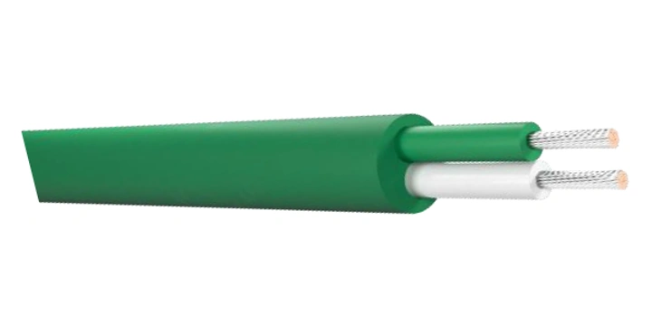
Conductors made of special metal alloys. Insulation and jacket: PVC, SiR, HFFR, FEP, PFA, fiberglass, or basalt fiber. CuSn shield; FeZn or AISI 304 reinforcement. The design depends on the agreed-upon specifications.
Standards
IEC 584-3; DIN 43714; BS 1843; NF C 42-324; ANSI/MC 96-1
Application
Compensation and extension cables (thermoelectric) are components of a measurement system that connect a thermoelectric sensor to a measuring device, such as a controller, indicator, or temperature recorder.
Technical Tables
Material Combinations and Operating Temperatures
| Insulation / Coating | Temperature [°C] |
|---|---|
| PVC / PVC | −25…+105 |
| SiR / SiR | −60…+200 |
| HFFR / HFFR | −40…+120 |
| FEP / FEP | −90…+205 |
| PFA / PFA | −90…+260 |
| GL / GL | −60…+400 |
| BB / BB | −60…+750 |
These are not thermocouple measurement ranges or compensation ranges. Mixed configurations require individual verification.
Available versions
The designation specifies the thermocouple type, insulation, conductor construction, jacket, shield, number of pairs, and conductor cross-section. The designation scheme covers 1–8 pairs and cross-sections of 0.22; 0.5; 0.75; 1; 1.5; 2.5 mm². This does not imply that every combination is available. The specific configuration is agreed upon on a case-by-case basis. The cable diameter is provided upon request.
Example: JX FEP L SiR EK 1 X 2 X 0.5. Types in the diagram: JX, TX, EX, KCA, KX, NX, R/SCA, BC. D = single-strand conductor; L = multi-strand conductor. Braid/shield: Q = galvanized steel wire; EK = tinned copper wire.